
| Basket: | empty | |
| Global Shipping | ||
 |
Void Infinite 8 mk1 Power Amplifier
 |
 |
 |
 |
 |
 |
 |
| Cairn K05 | A Big Motorhome | Beresford DAC | Void Infinite 8 | Wurlitzer Jukebox | Frank Zappa's Mixer | VAC Valve Amplifier |
Golliath 8kW power amplifier from manufacturers Void Acoustics almost completely destroyed. We replaced nearly all the active components inside the amplifier to bring it back to life again...
Please click on the images to enlarge
- Void Infinite 8 mk1 Power Amplifier had been almost completely destroyed inside. We suspect the output had been short-circuited whilst the amp was delivering full power, or was supplied from an unusually high mains voltage.
- Replaced almost everything inside the amplifier!
- Corrected design flaws in the amplifier where the VAS transistors, rated at 250V, were exposed to 360V DC, causing them to go into second breakdown.
- The cascode in the input stage was supplying 30V to the differential pair, but the transistors were only rated at 160V themselves.
- Running from a 185V rail does not allow sufficent mains voltage variation before the transistors encounter over-voltage (185V minus 30V = 155V, only 5V lower than maximum Vce).
- We raised the cascode voltage to 56V, while modifying the tail current source keeping differential pair current and transconductance constant, to allow sufficient headroom. Higher voltage transistors have worse gain and capacitance behaviour and would have not been ideal for such a sensitive stage.
- Uprated the output transistors to cope with more voltage and current: 2SC5200 / 2SA1943 replaced with MJL3281 / MJL1302 respectively.
- Uprated VAS transistors, uprated freewheeling diodes and uprated switching MOSFETs were fitted too, making the amp a lot more reliable and more tolerant to mains voltage variations.
- All output devices, drivers, pre-drivers, Vbe multiplier, protection circuitry, VAS transistor, VAS buffer, input stage transistors, input stage cascode, bias servo, input op-amp, clip limiter comparator, switching MOSFETS, switching MOSFETS driver, freewheeling diodes, all emitter degeneration resistors and lots of other passives were all completely replaced; such was the extent of the damage.
- Lots of other important tweaks carried out to improve reliability.
- Void Infinite 8 amplifier repair completed successfully after re-biasing and a bit of tweaking. Chucking out 2000W per channel into 4 ohms, or 8000W briged, certainly an amp worth taking seriously!.
- Total harmonic distortion at 1kW, 400Hz, 8Ohms was less than 0.05%, and less than 1% at 20kHz.
- High order harmonics present due to the switching action of the class G output stage.
Description of images:
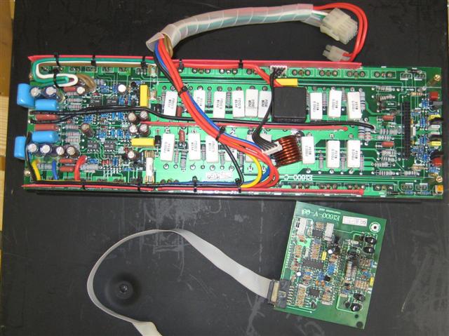
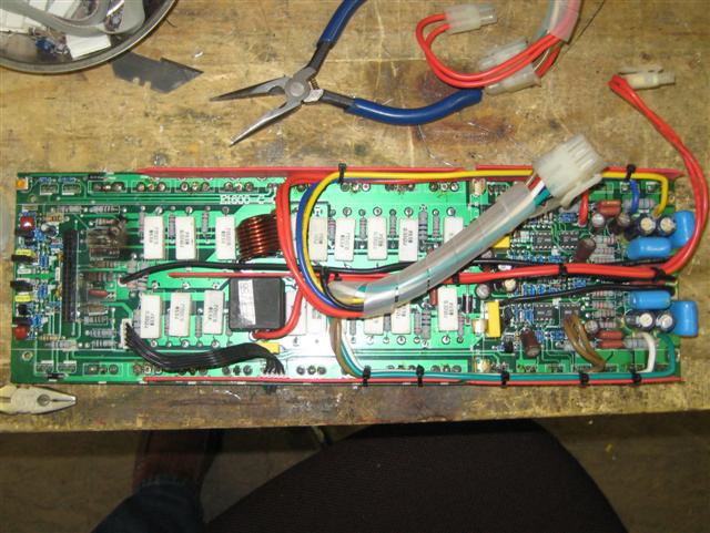
- One of the amplifier channels removed from the amplifier prior to the repair. The circuit board towards the bottom right contains the differential pair and VAS buffer transistors and clip limiting circuitry. There is substantial damage to the components where they have literally been on fire.
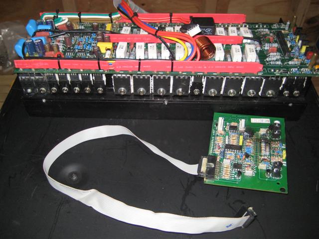
- Another shot of the amp channel this time showing one row of output transistors on the main heatsink. Most of these devices have failed, or were close to failure, causing a trail of destruction through the circuit right the way back to the input op-amp. On the far right of the main heatsink are the VAS transistors which were incorrectly rated for the voltages inside the amp.
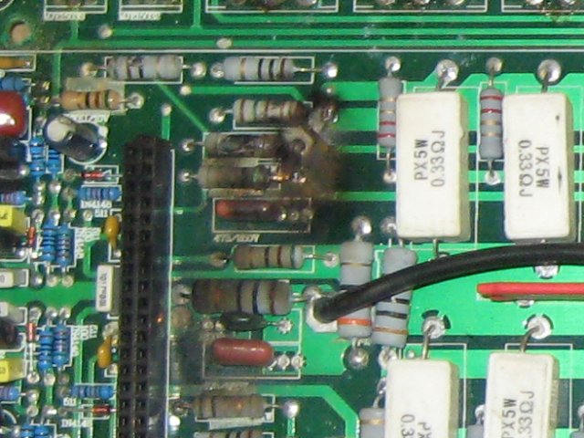
- Close up of the input board showing extensive damage. The other channel was worse.
- The same amp channel in isolation.
- The other channel showing extensive to the components towards the left hand side of the PCB.
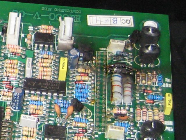
- Close up of some of the resistors that have literally exploded or acted like fuses.
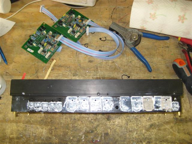
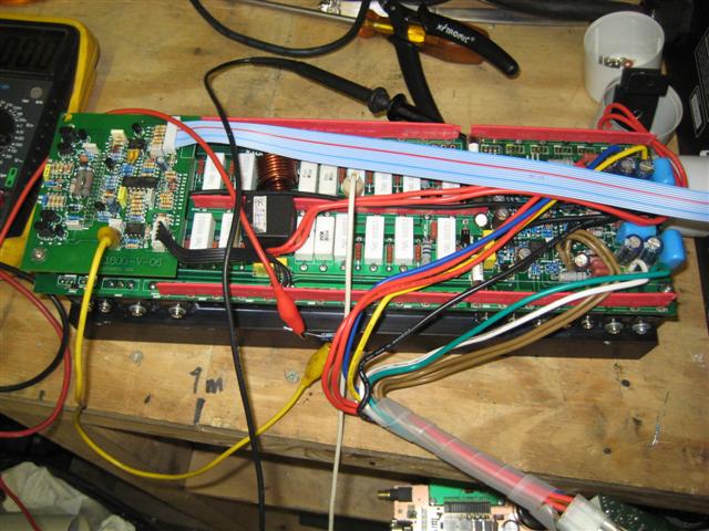
- Removing the output devices, freewheeling diodes, switching MOSFETS and VAS transistors from the main heatsink, prior to cleaning off the thermal transfer compound. Note the repaired input boards fitted with new ribbon cable and IDC connectors
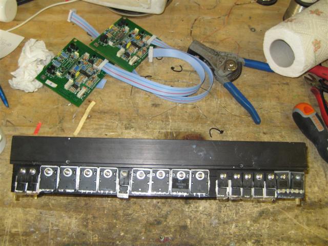
- Prior to removing the transistors from the other side of the heatsink...
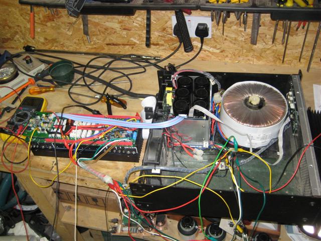
- Tentatively testing the re-assembled and repaired channel
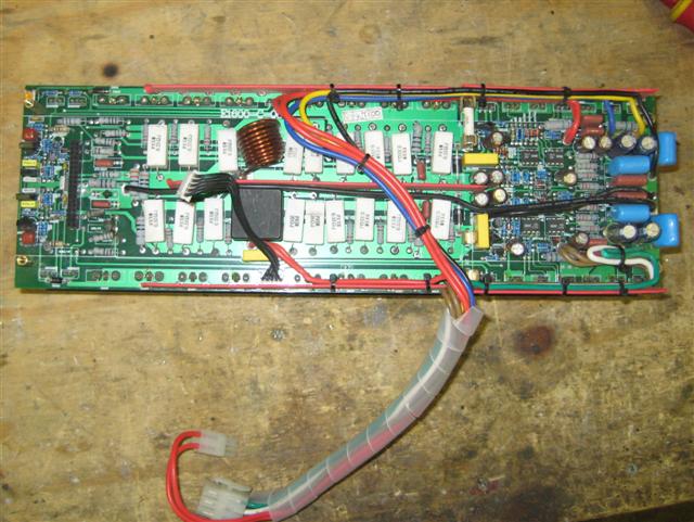
- Showing the completed repaired amp channel.
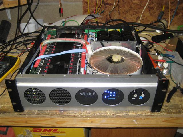
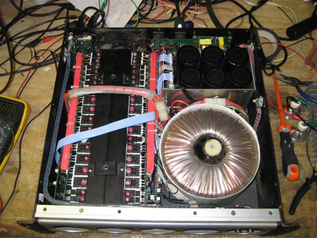
- The assembled amp on the test bench, after considerable checking and re-checking, running at full power.
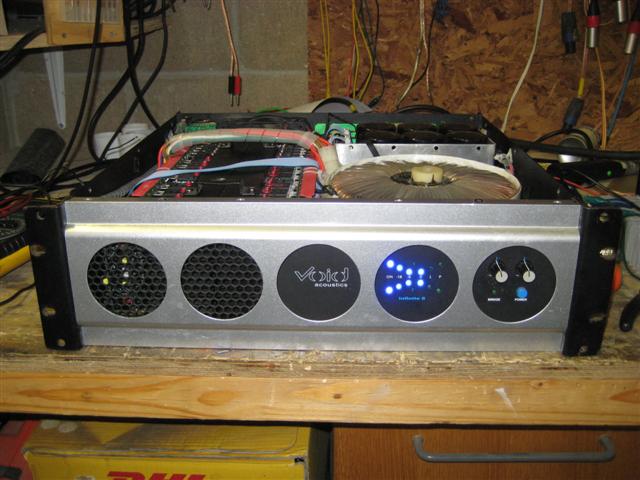
- Front of the amplifier running at full power.
- Lid off the amplifier. The red stuff on the transistor mounting screws prevents vibration loosening them.
- Distortion performance of the completed and re-biased amplifier at half-power, showing less than 0.05% at 417Hz. Not bad for a complete re-build.
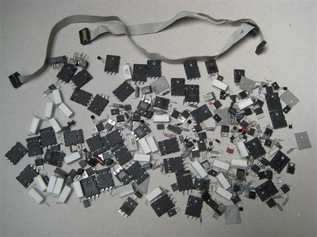
- This is what we took out - the greatest number of parts we've ever replaced in a amplifier!
^ Back
×
