
| Basket: | empty | |
| Global Shipping | ||
 |
Peavey IPR-1600 Amplifier Test Results
Very budget Class D amp from Peavey
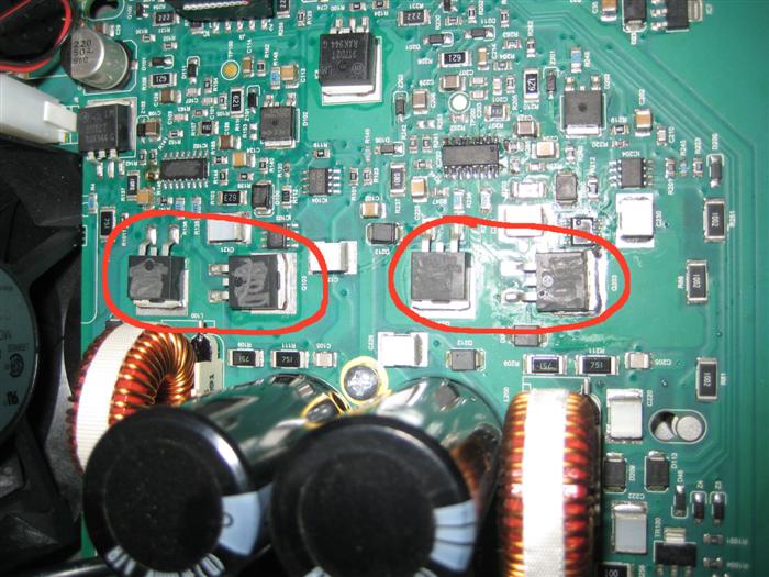
Lightweight and budget Class D amplifier from Peavey featuring internal blue casework illumination and blue illumination of the Peavey logo. Nice. Very flimsy aluminium casework and cheap input and output sockets. However, very well production-engineered giving the amplifier an extremely low retail price. Part numbers cryptically ablated (ground off) from the surface of the Class D controller ICs and the output devices.
Waveform performance is good, a small amount of disturbance is present at the waveform crests prior to clipping at all frequencies, and the amplifier clips reasonably well. Overdriving the amplifier input stage (4V or more) causes severe distortion, otherwise distortion is very low. I measured no more than 0.1% at all frequencies at 8R and 4R loading, at 3/4 power. Full power measurements are given in the table below.
*2R ratings: The upper figures in the 2R column of the table represent 'continuous' sine ratings into 2R at respective frequencies. The mechanical circuit breaker on the rear of the unit tripped repeatedly when subjected to 2R loading, both channels driven, and as such this figure should be considered a 1 second rating. The lower figure in the table, with *, is a ONE-CHANNEL-DRIVEN 2R 100ms burst rating. It is the most amount of power we could obtain from the amp at the threshold of clipping, before power supply limiting and tripping of the circuit breaker. 4R continuous sine also tripped the rear breaker, but only after several tens of seconds. In a music scenario, average current will be lower.
|
All results taken with sine wave input into a resistive dummy load of 8, 4 and 2 ohms (where applicable), two channels simultaneously driven (unless otherwise stated), at the threshold of clipping. These results should be considered maximum 'continuous RMS' power ratings (>5 seconds). Distortion measurements, labelled THD%, are taken with an HP8903A audio analyser (80kHz Bandwidth). | |||||||||||||||||||||||||||||||||||
| Manufacturer | Peavey |
|---|---|
| Model | IPR-1600 |
| Weight | 5 kg |
| Power to weight Ratio1 | 213.2 W/kg |
| Notes | Tested 03-07-2010. Good performance, good clipping behaviour and low distortion when not cipping. Mains hovered about 241V throughout testing. Mains circuit breaker repeatedly tripped during 4R sine testing, and tripped quicker during 2R testing. Hence the single-channel driven burst results as given above. |
| Manufacturer's Website | http://www.peavey.com |
1 Power to weight ratio is calculated by taking the average of the power measurements at 4 ohms, multiplying by the number of driven amp channels, and then dividing this value by the weight of the amplifier.
Click the images below for full-size versions
Description of Images:
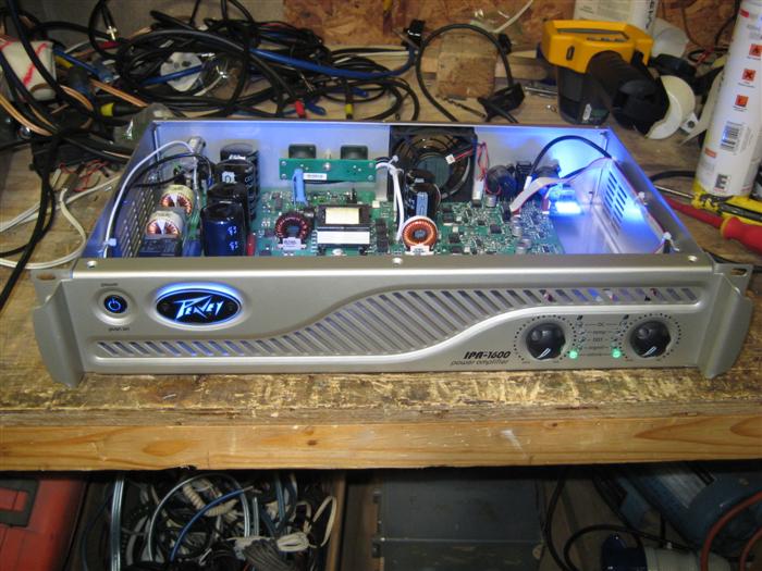
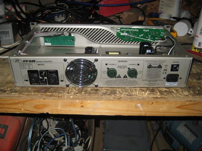
- The amplifier sits quiescent on a messy bench.
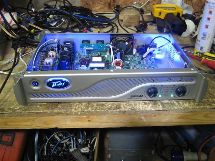
- Another shot of the amp. Note the internal illumination.
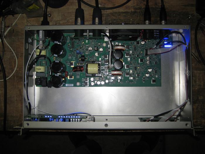
- Amp internals.
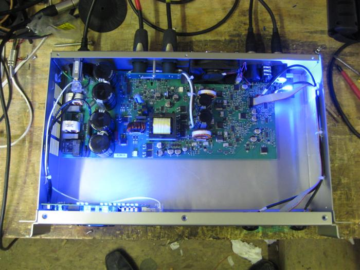
- More amp internals.
- Ablated chips and surface-mount output devices (circled).
- Rear of amplifier case.
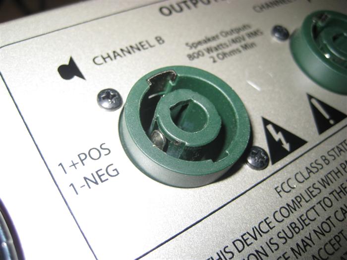
- High profile Speakon-compatible sockets. These are not made by Neutrik.
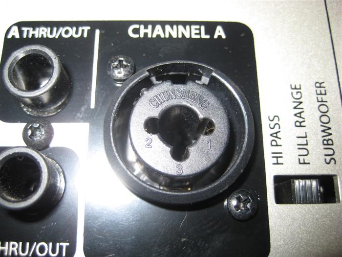
- Very cheap combi input connectors.
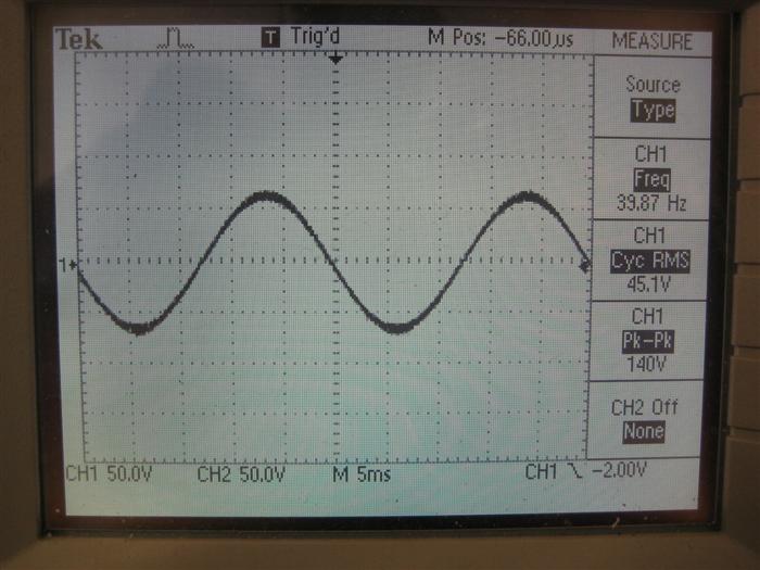
- 40Hz Sine wave, 4R, threshold of clipping. Very good, a little evidence of switching residual bleed-through.
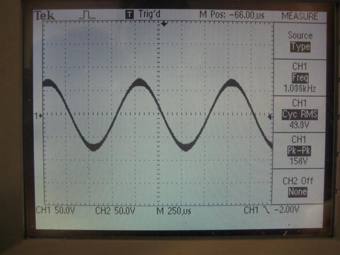
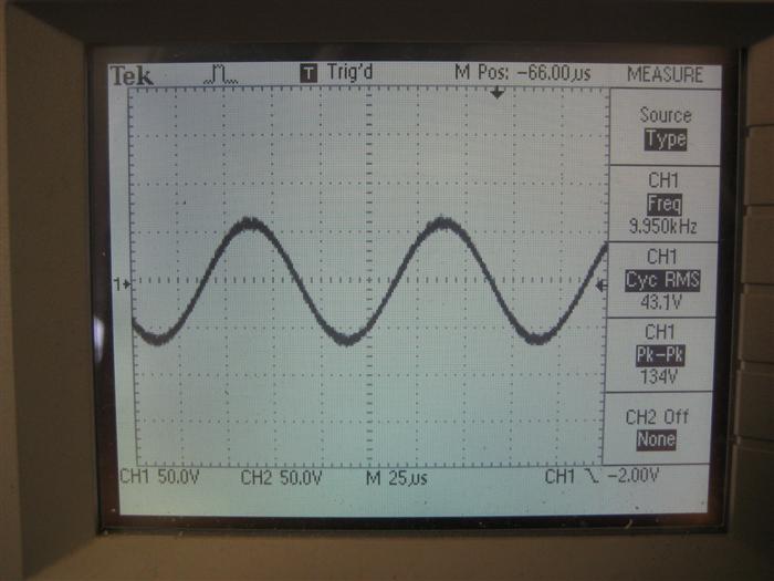
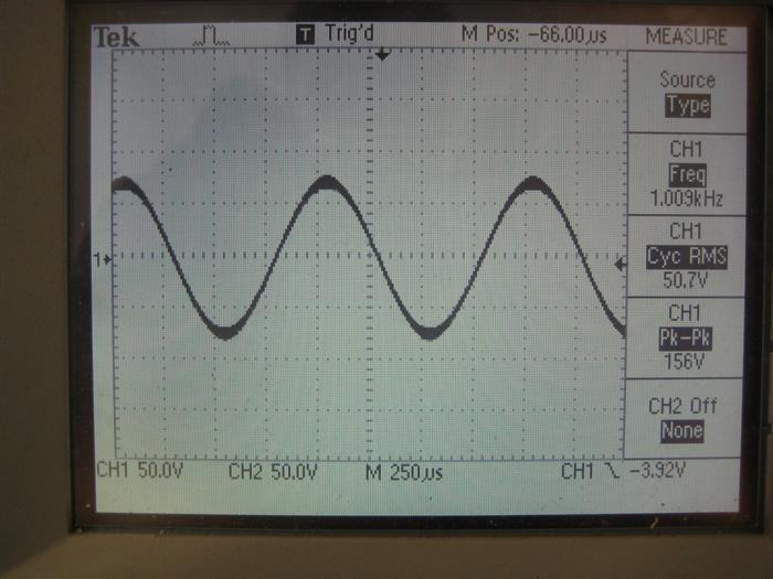
- 1kHz Sine Wave, 8R, threshold of clipping. Again, very good, a small amount of residual bleed-through.
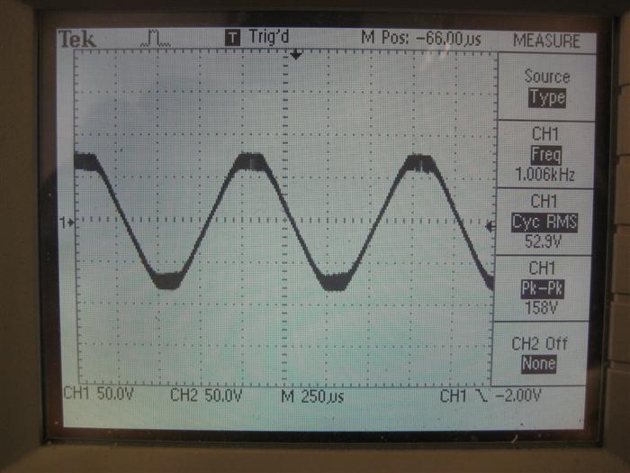
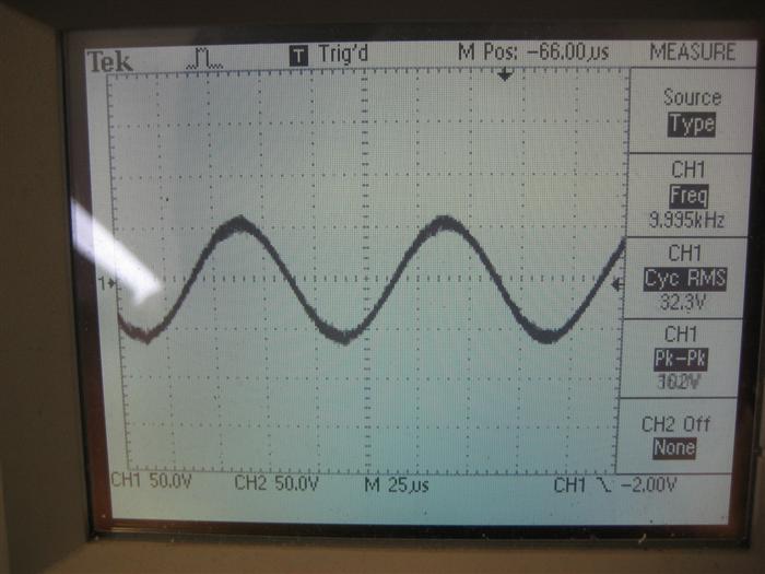
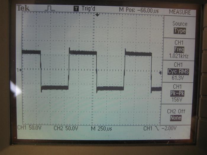
- 1kHz Sine wave, 8R at clipping. Evidence of residual bleed-through on crests of waveforms. Very high frequency, hence the thickened crests.
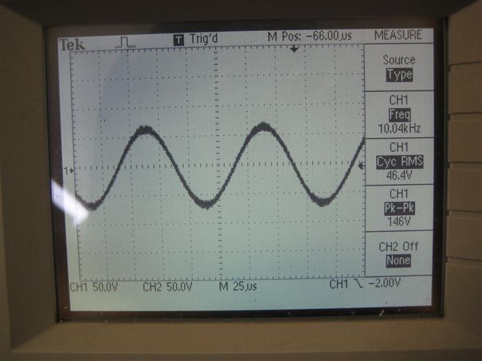
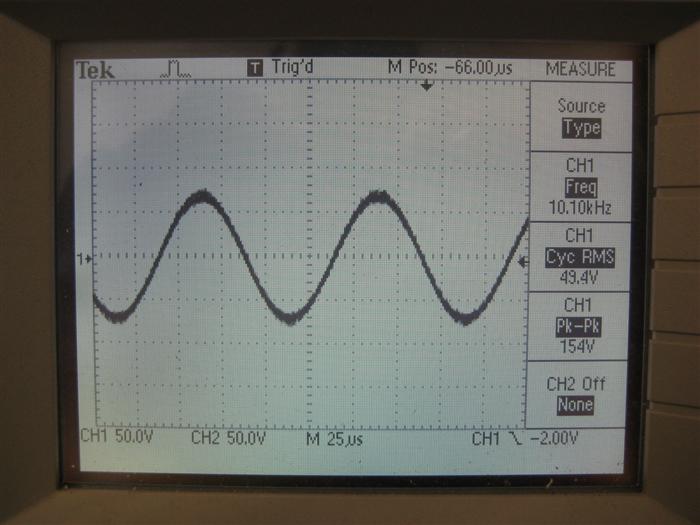
- 10kHz Sine Wave, 8R, threshold of clipping. Very good, minimal distortion and residual artefacts.
- 10kHz Sine wave, 8R, threshold of clipping. Very good, minimal distortion and residual artefacts.
- 10kHz Sine wave, 2R, one channel driven, threshold of clipping, 100ms burst. Again, very good.
- 10kHz Sine wave, 2R, both channels driven, threshold of clipping, 1 second burst. Again, very good.
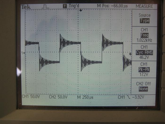
- 1kHz square wave, 4R, threshold of clipping (measured to limitation of ringing).
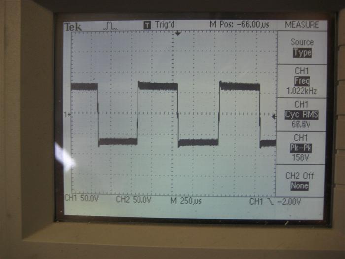
- 1kHz square wave, 8R, threshold of clipping (measured to limitation of ringing).
- 10kHz square wave, 4R, threshold of clipping. Very slight ringing and slow-ish rise time.
- 10kHz square wave, 8R, threshold of clipping. More ringing here, shows underdamped output filter at higher load impedances
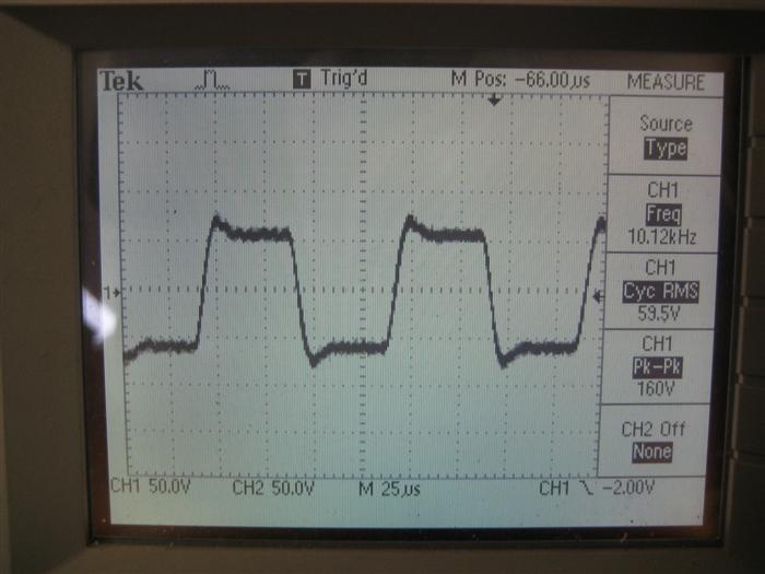
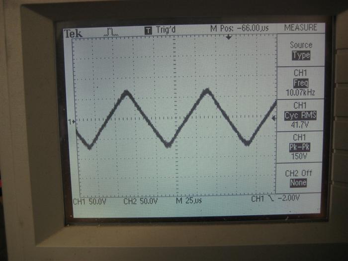
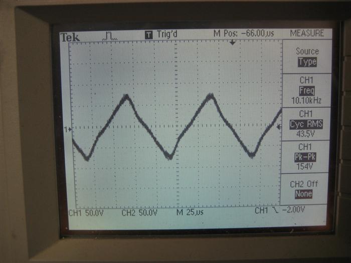
- 10kHz triangle wave, 4R, threshold of clipping.
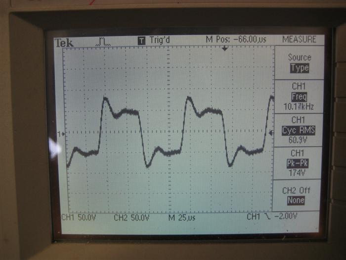
- 10kHz triangle wave, 8R, threshold of clipping. Visible distortion due to underdamped output filter.
- 1kHz square wave, open circuit, threshold of clipping. Shows prolonged decaying ringing due to underdamped output filter.
- 1kHz sine wave, open circuit, threshold of clipping. Excellent, almost no visible distortion.
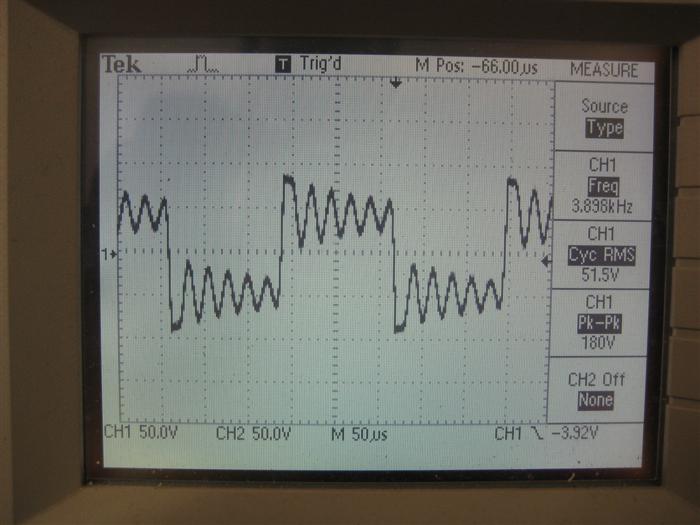
- 4kHz square wave, open circuit. Prolonged ringing clearly visible.
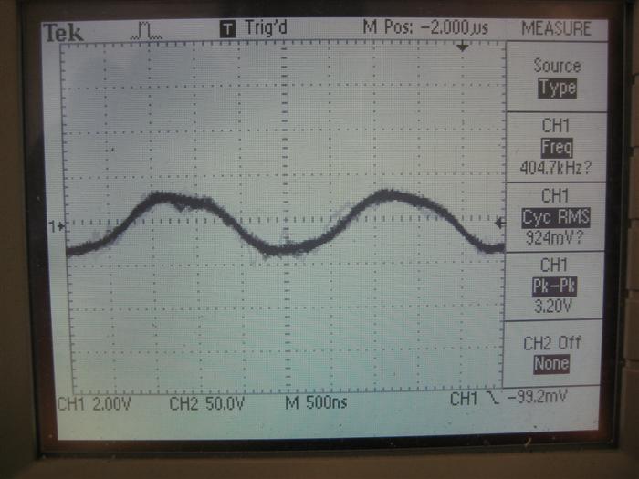
- Quiescent output residual, 8R, no input. Sinusoidal in shape, and no EMI nasties. A little high at nearly 1V rms, however. Approx 400kHz switching frequency is used in this amplifier.
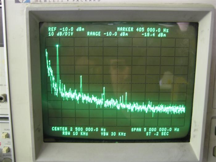
- Quiescent output residual, 8R, spectrum. Clearly shows 400kHz switching frequency and harmonics thereof. Spectrum decays into noise above 3MHz. No EMI issues here.
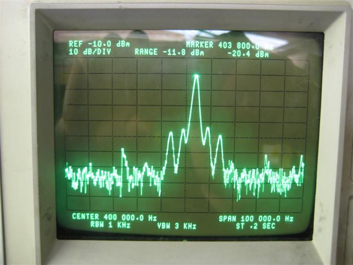
- Quiescent output residual, 8R, no input, spectrum showing sidebands.
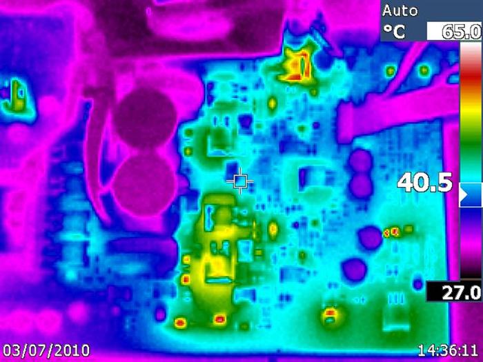
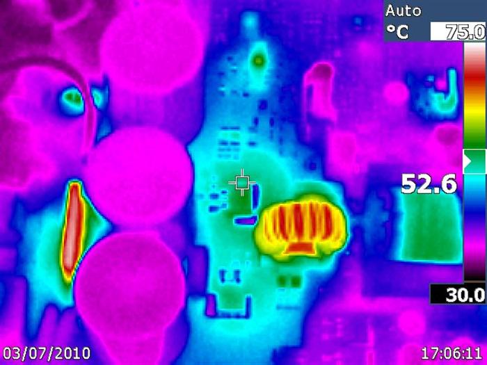
- PCB thermal image, showing the amplifier quiescent and warmed up after 20 mins. Output devices furthest away from the fan are slightly hotter despite the fan running at incredibly slow speeds when idle. Minimal airflow does seem to make a difference. Note the temperature scale to the right of the image. This image shows the right-hand side of the PCB.
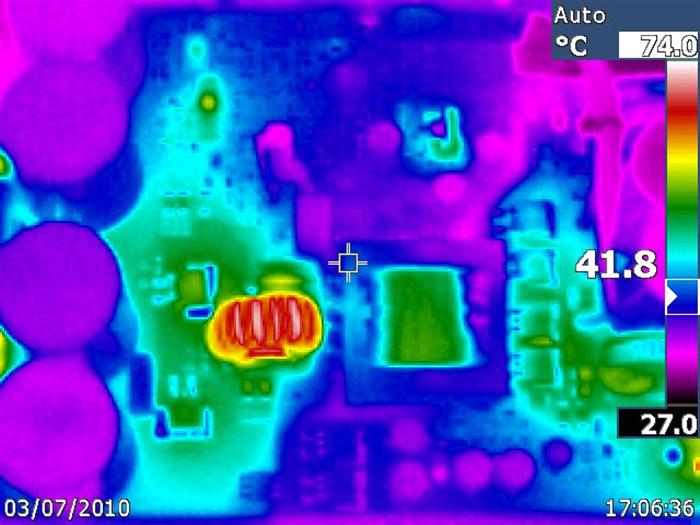
- PCB thermal image, 3/4 power, 4R load. Left hand side of PCB showing Bridge rectifier and primary-side smoothing. Series resonant inductor is hot, the inductor core is hotter. SG3525 controller IC towards the top of the image is running warm.
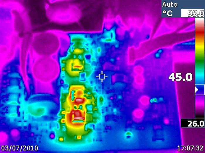
- PCB thermal image, 3/4 power, 4R load. Middle of PCB shows the SMPS transformer and secondary rectification.
- PCB thermal image, 3/4 power, 4R load. Right hand side of PCB, showing output devices closer to the fan are coolest. During operation there is a cowl diverting airflow over the output devices which has been removed for this test.
