
| Basket: | empty | |
| Global Shipping | ||
 |
QSC PLX3002 Amplifier Test Results
Lightweight and powerful amplifier from QSC
Good-performing amplifier in a lightweight and compact package, features internal switchable low-pass filters and clip limiting. Good performance, low distortion and low weight.
|
All results taken with sine wave input into a resistive dummy load of 8, 4 and 2 ohms (where applicable), two channels simultaneously driven (unless otherwise stated), at the threshold of clipping. These results should be considered maximum 'continuous RMS' power ratings (>5 seconds). Distortion measurements, labelled THD%, are taken with an HP8903A audio analyser (80kHz Bandwidth). | |||||||||||||||||||||||||||||||||||
| Manufacturer | QSC |
|---|---|
| Model | PLX3002 |
| Weight | 8 kg |
| Power to weight Ratio1 | 291.3 W/kg |
| Notes | Mains hovered about 242V. 22-07-2010 |
| Manufacturer's Website | http://www.qscaudio.com/ |
1 Power to weight ratio is calculated by taking the average of the power measurements at 4 ohms, multiplying by the number of driven amp channels, and then dividing this value by the weight of the amplifier.
Click the images below for full-size versions
Description of Images:
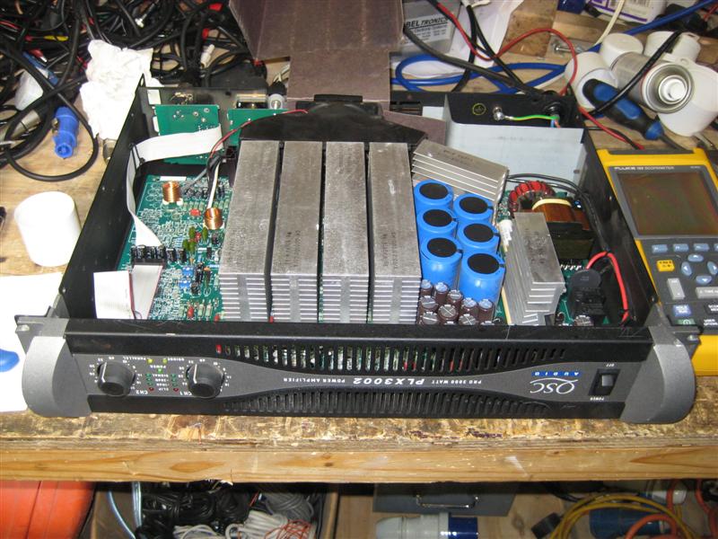
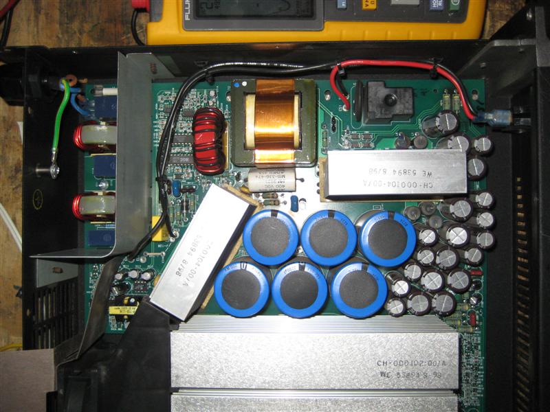
- Amplifier internals and front panel. Note the circuitry hangs upsidedown in the casework.
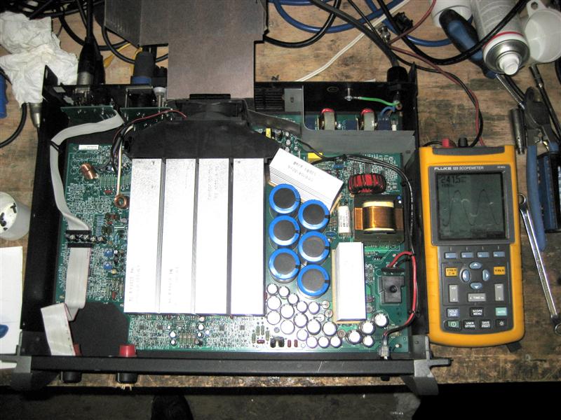
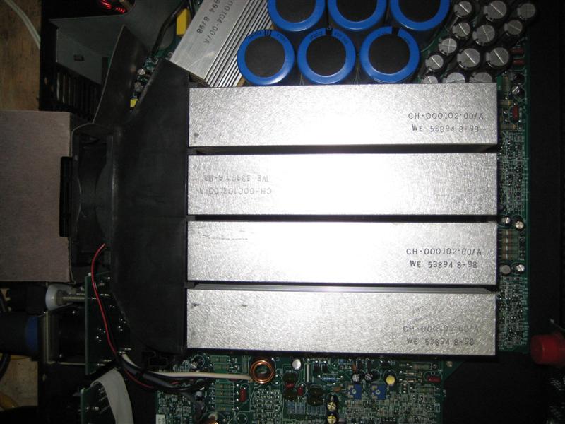
- Amplifier top view. The switched-mode power supply sits towards the right of the image and the amplifier circuitry sits under, and to the left of, the four heatsinks in the middle.
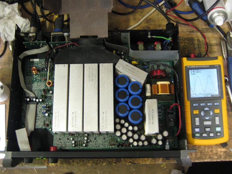
- Another shot of the internals. The scopemeter shows the mains voltage and waveform (full power, 4R).
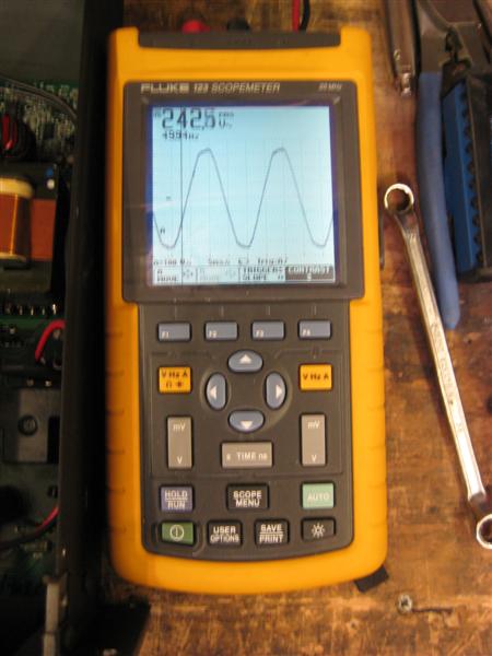
- Mains voltage and waveform (full power, 4R). Harmonic distortion of the mains is clearly visible, and is better when the amplifier is not running. This is due to the poor power factor of non-PFC power supplies operating from a finite mains impedance.
- Close-up of the switched-mode power supply.
- The four amplifier 'live' heatsinks connected to the output signal.
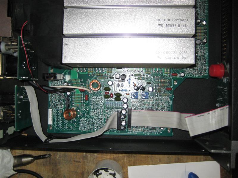
- Amplifier driver circuitry showing a mixture of surface-mount and through-hole components.
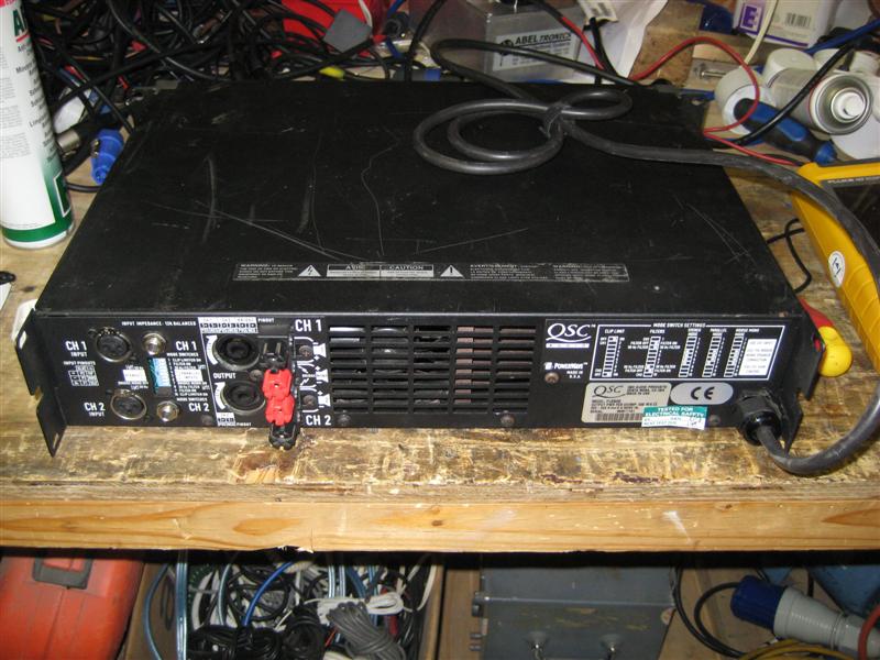
- Rear of amplifier case.
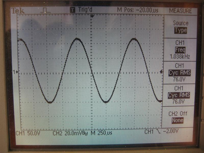
- 1kHz, 4R, full power. Perfect.
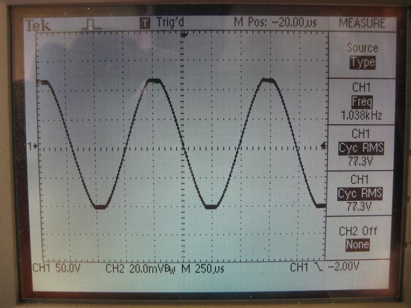
- 1kHz, 4R, clipping. Excellent behaviour with no nasties or parasitics.
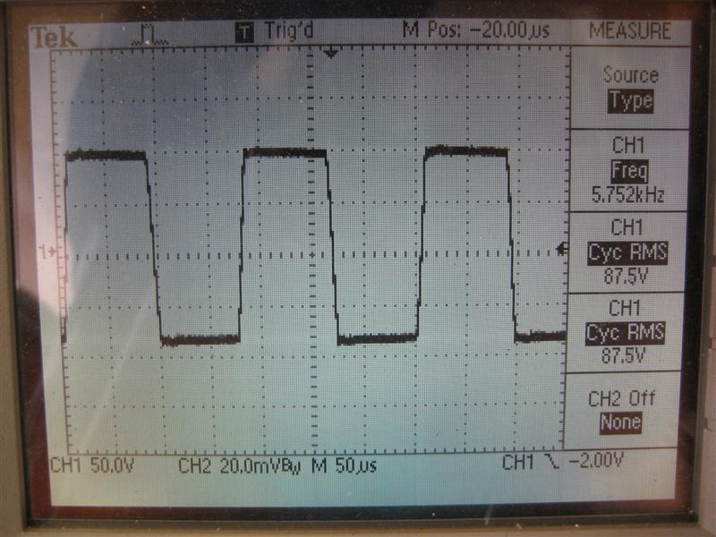
- 6kHz square wave, 4R, full power. Slow-ish rise and fall times, but excellent performance with no overshoot or ringing.
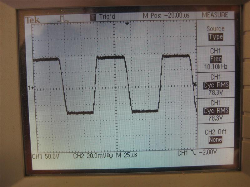
- 10kHz square wave, 4R, full power. Again, slow-ish rise and fall times (approx 17v/us), but excellent performance with no overshoot or ringing.
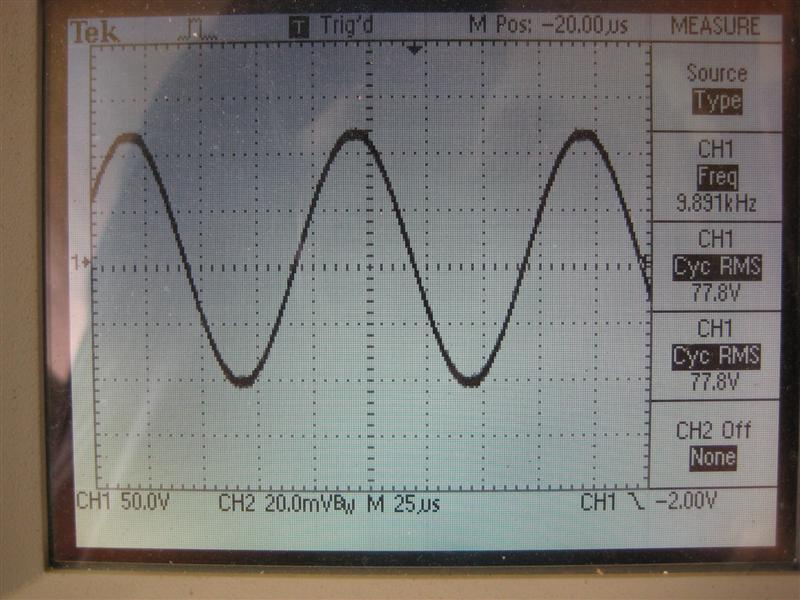
- 10kHz, 4R sine wave, threshold of clipping. Very good indeed.
×
