
| Basket: | empty | |
| Global Shipping | ||
 |
MC2 Audio MC650 Amplifier Test Results
Excellent Hi-fi grade amplifier from MC2
Excellent amplifier from MC2 showing particularly low harmonic distortion, very low noise and very low DC offset. DC offset was measured at 0.95mV and -2.27mV on channels A and B respectively which are astounding figures for a PA amplifier. The low offset suggests a well implemented bias servo. Sine wave performance was excellent at all frequencies and load impedances, and square wave and triangle wave performance (not shown below due to lack of time) was also excellent.
The amp has an extremely beefy power supply and the huge toroidal transformer makes up the vast majority of the weight of the unit. Halving the load impedance from 8R to 4R almost doubles the amp's output power, in part due to the very stiff power supply, but output power drops off with 2R loading as the amplifier limits its output current. The amplifier has a load impedance switch on the rear, leaving it in the 8R/4R position yields higher power at 2R load, but I suspect this configuration is not recommended. The 2R power given below is measured with the switch set to the 2R/4R position.
The distortion of this amplifier is so low that I felt it necessary to include the last decimal place shown on the distortion analyser in these results. It is usually rounded off. The distortion residual showed mostly odd-order harmonic content and possible evidence of some crossover distortion, although the levels are exceedingly low. The distortion increased very slightly under prolonged load and increased heatsink temperature (we measured 0.038% at 2R initially, increasing to 0.059% after 10 seconds) possibly due to thermal lag in the output device bias network, but these changes are absolutely negligible and are of little significance in practice. Both channels had identical outputs, within 20mV, when fed with the same input signal at maximum gain.
The level controls on the front of the amplifier are rotary encoder types - the gain is controlled by a pair of high quality PGAs (programmable gain amplifiers) made from an R-2R DAC around the feedback loop of an op-amp - the audio signal does not pass through the front panel controls. These controls can be fiddly to operate and it is not immediately obvious to what gain the amp is set. The four 80mm axial cooling fans, two per channel, are very effective and very quiet in operation, and only cut in when the heatsink temperature exceeds about 65 degrees. Air is sucked in through the front panel foam filter grille and exhausted on opposite sides of the amplifier.
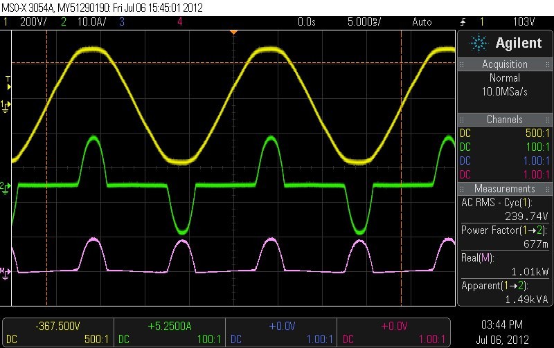
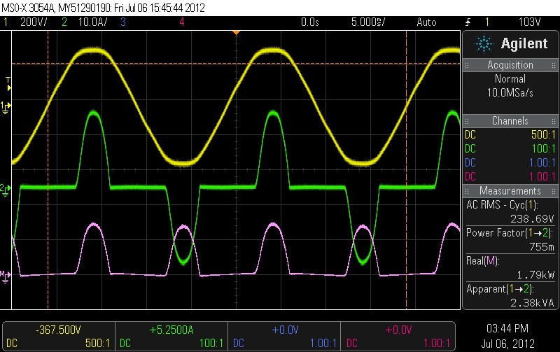
The power factor and mains current draw of the amplifier is as expected for a toroidal design (the humpy mains current waveforms shown below are due to the reservoir capacitors charging on the peaks and troughs of the rectified output from the transformer and is normal for a toroidal design). There are no EMI issues or other high frequency nasties polluting the mains, although powering a large rack of these amplifiers from an undersized generator is best avoided.
We restricted testing at 2R impedance to 1kHz at the owner's request.
All in all, very impressed. One of the best amplifiers we've ever seen in terms of distortion and noise performance, and certainly the best performing PA amp we've measured so far.
Mains voltage connected to scope with an Agilent N2790A differential probe, current measured with an Agilent N2781B current probe. Audio signal waveforms are shown on an Agilent MSO7104B 1GHz oscilloscope with mains waveforms simultaneously captured on an Agilent MSOX3054A 500MHz oscilloscope.
|
All results taken with sine wave input into a resistive dummy load of 8, 4 and 2 ohms (where applicable), two channels simultaneously driven (unless otherwise stated), at the threshold of clipping. These results should be considered maximum 'continuous RMS' power ratings (>5 seconds). Distortion measurements, labelled THD%, are taken with an HP8903A audio analyser (80kHz Bandwidth). | |||||||||||||||||||||||||||||||||||
| Manufacturer | MC2 Audio |
|---|---|
| Model | MC650 |
| Weight | 20.5 kg |
| Power to weight Ratio1 | 61.0 W/kg |
| Notes | Tested on 6th July 2012. Mains voltage hovered around 240V AC. |
| Manufacturer's Website | http://www.mc2-audio.co.uk/ |
1 Power to weight ratio is calculated by taking the average of the power measurements at 4 ohms, multiplying by the number of driven amp channels, and then dividing this value by the weight of the amplifier.
Click the images below for full-size versions


Description of Images:
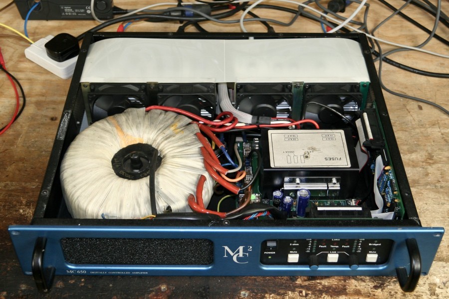
- Amplifier internals. Note the huge toroidal transformer taking up the lower quadrant of the enclosure. The amplifier channels are at the back of the case, their heatsinks are covered with protective plastic.
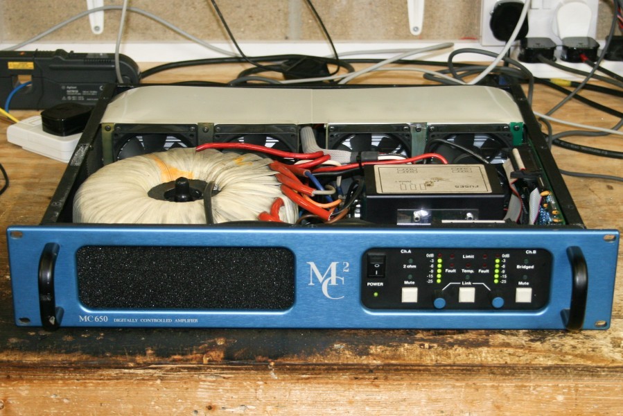
- Amp internals and front. Filter grille on the left, power and level controls on the right.
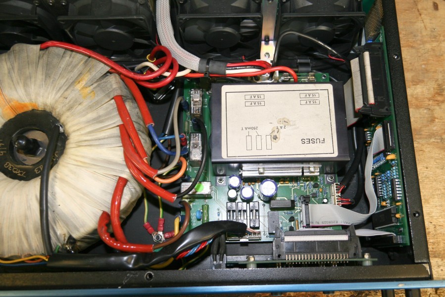
- Transformer and power supply PCB. Lots of rail smoothing under the labelled heatsink.
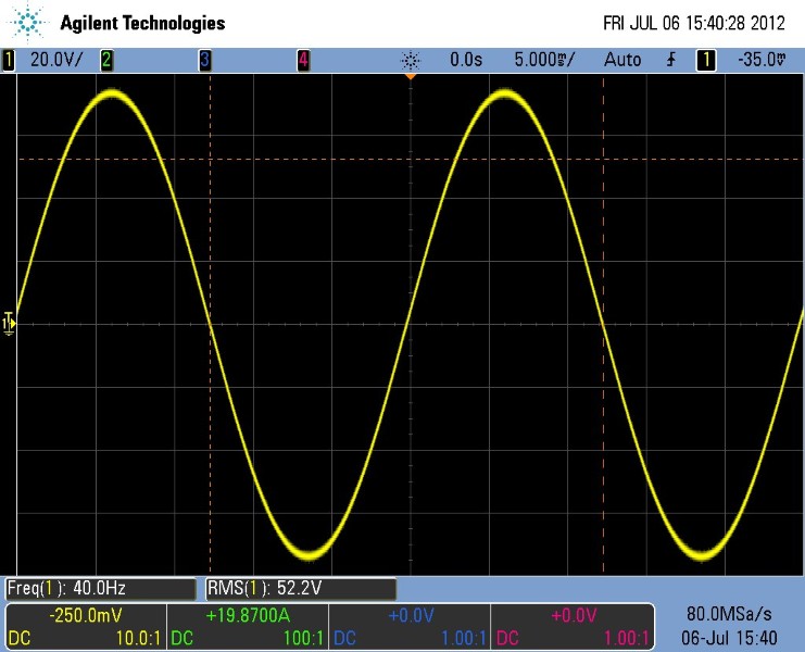
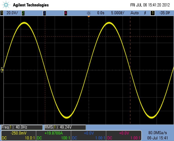
- 40Hz, 8R sine wave. Excellent performance.
- 40Hz, 4R sine wave. Excellent performance.
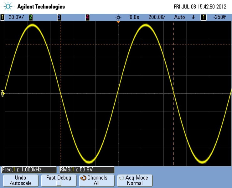
- 1kHz, 8R Sine wave.
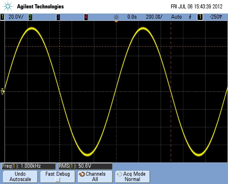
- 1kHz, 4R Sine wave.
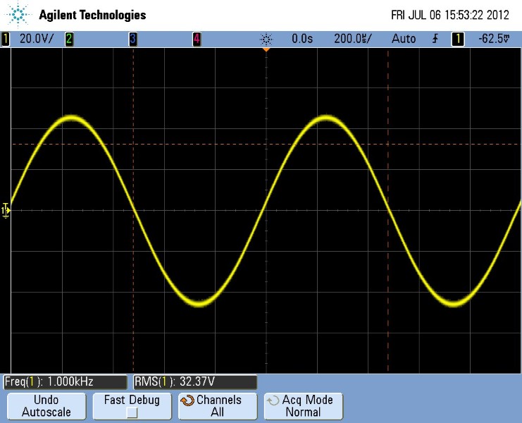
- 1kHz, 2R Sine wave. The amp appears to current limit here (rear panel switches set to 2R).
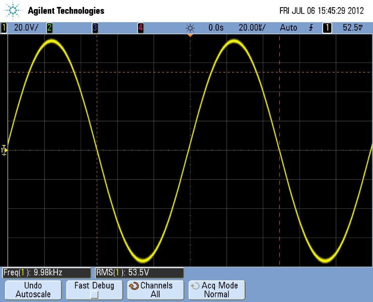
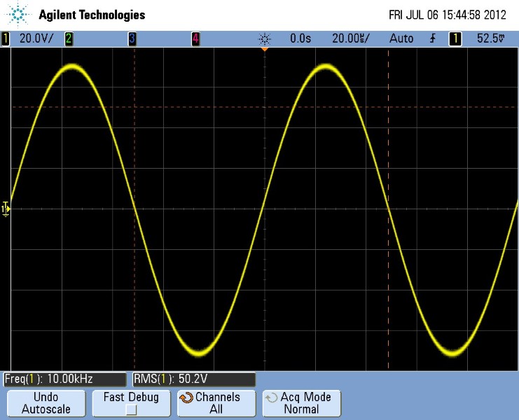
- 10kHz, 8R sine wave. Very good indeed.
- 10kHz, 4R sine wave. Very good indeed.
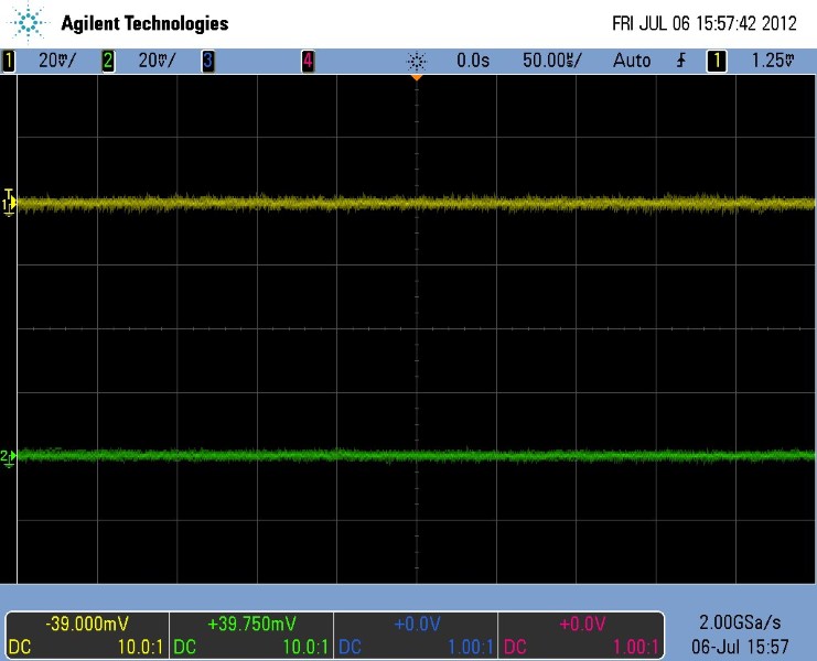
- Output DC offset - barely measurable on the scope (scope set to high resolution acquisition to minimise noise). We used the HP3456A bench multimeter to get the offset values.
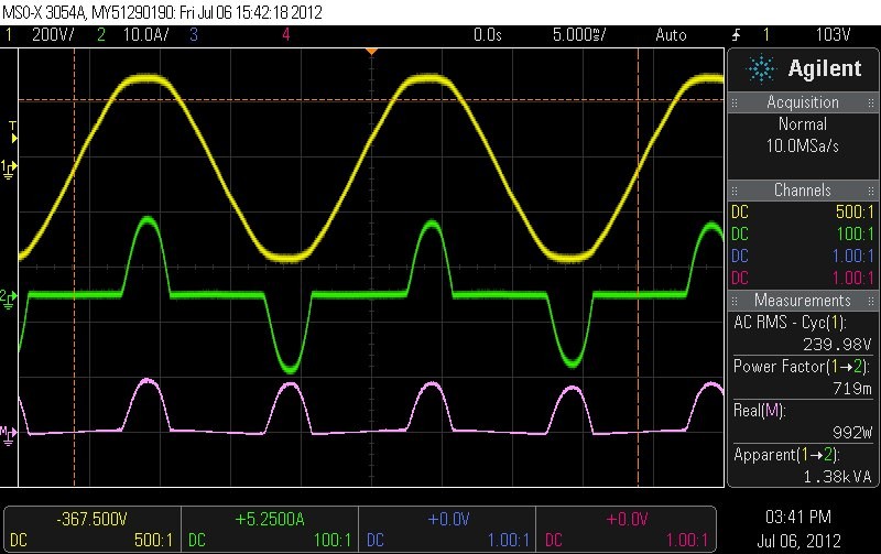
- Mains waveforms, 40Hz 8R load. Yellow waveform is mains voltage, green is mains current and pink is the instantaneous power. Power factor and power consumption are shown towards the right.
- Mains waveforms, 40Hz 4R load. Yellow waveform is mains voltage, green is mains current and pink is the instantaneous power. Power factor and power consumption are shown towards the right.
- Mains waveforms, 1kHz 8R load. Yellow waveform is mains voltage, green is mains current and pink is the instantaneous power. Power factor and power consumption are shown towards the right.
- Mains waveforms, 1kHz 4R load. Yellow waveform is mains voltage, green is mains current and pink is the instantaneous power. Power factor and power consumption are shown towards the right.
- Mains waveforms, 1kHz 2R load. Yellow waveform is mains voltage, green is mains current and pink is the instantaneous power. Power factor and power consumption are shown towards the right.
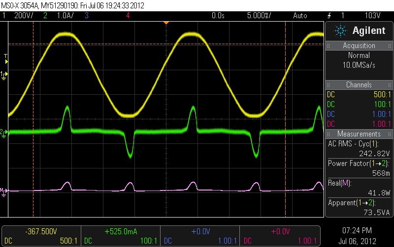
- Mains waveforms, idle (no input, no load). Current waveform vertical scale adjusted from previous measurements. Yellow waveform is mains voltage, green is mains current and pink is the instantaneous power. Power factor and power consumption are shown towards the right.
