
| Basket: | empty | |
| Global Shipping | ||
 |
Lexon / SAE PXM1450 Amplifier Test Results
Well constructed Class 'I' amplifier from Chinese brand Lexon / SAE
A very well built amplifier offering good performance and high power in a 2U rack.
The amplifier is a form of class G with the variable supply rails derived from switched-mode buck converters. This improves efficiency considerably over a traditional class G design and allows for a reduction in heatsink size and cooling requirements for a given amplifier power. This is at the expense of increased out-of-bound noise which is present on the output. Although this noise did not affect the distortion analyser, there is debate as to whether this noise is of any audible significance. The manufacturer calls this configuration 'Class-I'.
The internals of the amp are well laid-out, wiring is kept to a minimum but the design is still fairly modular. High quality components are used throughout.
Performance is generally acceptable given the amp's price point, and distortion is low for all frequencies and load impedances we measured. However, the power tails off significantly at 10kHz, prolonged sinewave output at this frequency causes the amp to go into protect with the 'Thermal' LED on the front panel illuminated. For this reason, no power measurements were taken at 10kHz into 4R or 2R - the amp didn't seem to like it.
Burst performance into 2R loading is very good, we measured almost 5kW peak per channel, with both channels driven at 1kHz, for a burst of 12ms duration (image 14 below). Transient response should be very good indeed, although it's questionable whether such a burst capability at 1kHz would be of any benefit in practice. Burst power at 40Hz was not so good, tailing off to just over 3kW per channel. These ratings are marked with an asterisk * in the table below. More prolonged 2R loading causes very little increase in power over the 4R values at 1kHz, at 40Hz the power was actually lower. The amp protects itself well against sustained 2R loading.
Prolonged output at 2R at any frequency, one or both channels driven, caused the amp to blow its internal fuses. A replacement fuse was all that was required. This in itself is almost unusual, output devices normally sacrifice themselves to save the fuses and a blown fuse often necessitates an involved repair. Waveform 11 below shows the amp running from a 13A supply, the amp blew the (slightly warm!) mains fuse within less than half a second with a load of 40Hz at 2R. At no point during testing did the mains breaker on the back of the unit trip, either plug fuses or internal fuses blew. The fact that the amplifier suffered no damage during testing, and fuses protected the circuitry as designed, is encouraging.
We were unable to get a THD reading at full power 2R, because the amp could not produce a signal long enough for the analyser to get a reading. At lower powers, where the analyser could lock on, we measured in the region of 0.15% at 1kHz.
When the amp arrived with us, one of the inrush protection surgistors had exploded even though the amp was almost brand new. We repaired this before carrying out the test.
Channel 2 is antiphase to channel 1, a common trick with some amplifier brands to get the most out of the power supply on (substantially mono) bass notes. This is corrected at the output by internally wiring the speakons and binding posts out of phase (the inverted signal drives the negative output thereby cancelling the phase shift). This fact, coupled with the reduced burst performance at 40Hz 2R, could indicate slightly undersized smoothing capacitors.
As long as the amp is kept at 4R load impedance or more, and is used at frequencies lower than 10kHz, performance and reliability should be very good.
Mains voltage connected to scope with an Agilent N2790A differential probe, current measured with an Agilent N2781B current probe. Audio signal waveforms are taken via a Metrix MTX1032-B dual differential probe and shown on an Agilent MSO7104B 1GHz oscilloscope. Mains waveforms simultaneously captured on an Agilent MSOX3054A 500MHz oscilloscope.
|
All results taken with sine wave input into a resistive dummy load of 8, 4 and 2 ohms (where applicable), two channels simultaneously driven (unless otherwise stated), at the threshold of clipping. These results should be considered maximum 'continuous RMS' power ratings (>5 seconds). Distortion measurements, labelled THD%, are taken with an HP8903A audio analyser (80kHz Bandwidth). | |||||||||||||||||||||||||||||||||||
| Manufacturer | Lexon / SAE |
|---|---|
| Model | PXM1450 |
| Weight | 24.4 kg |
| Power to weight Ratio1 | 90.6 W/kg |
| Notes | Tested on 17th October 2014. Mains hovered around 240V - see power waveforms. Internal fuses blew and were replaced |
| Manufacturer's Website | http://www.lexonpro.com/ http://www.saeaudio.com/ |
1 Power to weight ratio is calculated by taking the average of the power measurements at 4 ohms, multiplying by the number of driven amp channels, and then dividing this value by the weight of the amplifier.
Click the images below for full-size versions
Description of Images:
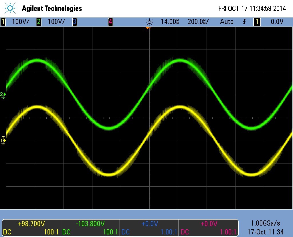
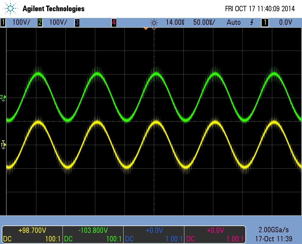
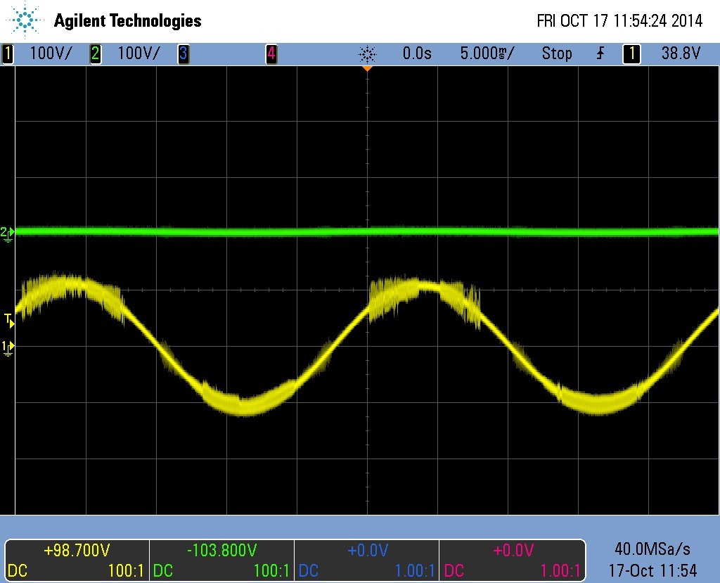
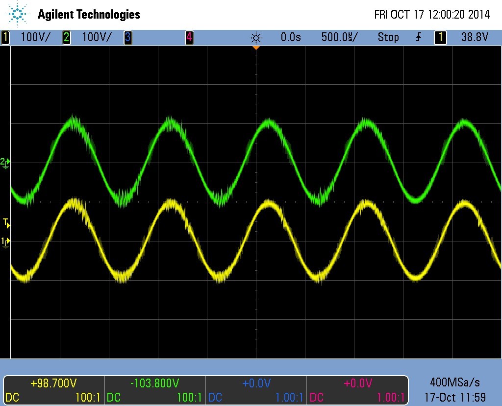
- 40Hz 8R Sinewave, clean looking, some evidence of high-frequency bleed-through from the switched mode rail drivers
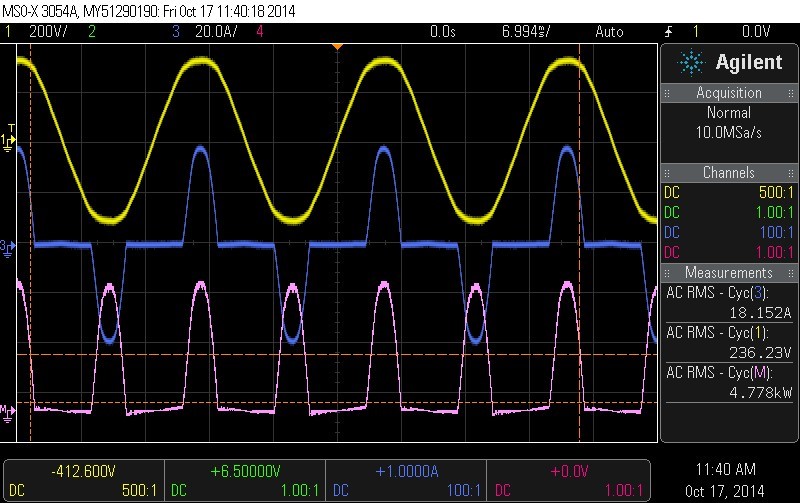
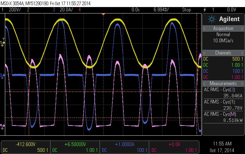
- Mains power waveforms for 40Hz, 8R. Yellow trace is mains voltage, blue trace is mains current, pink trace is mains power. Typical power factor for a toroidal amplifier, no high-frequency switching harmonics present on the current waveform.
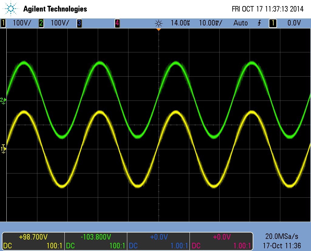
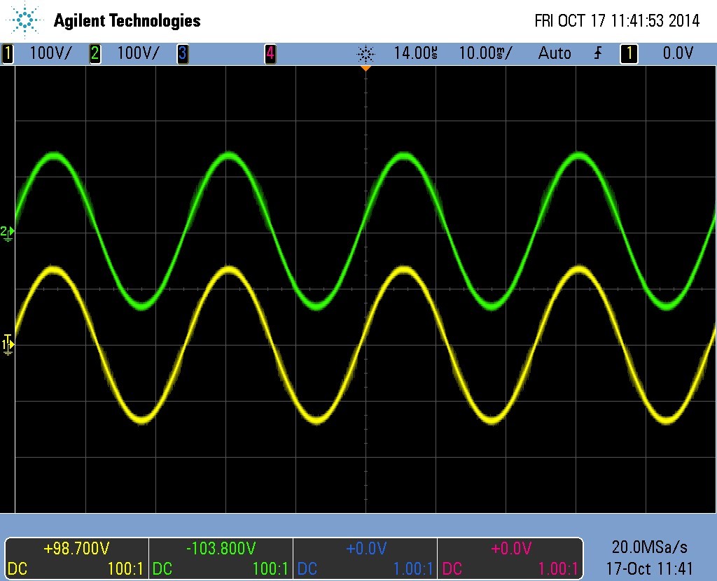
- 1KHz, 8R. More evidence of switching noise on the edges of the waveform, otherwise clean.
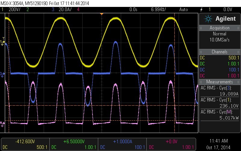
- Mains power waveforms for 1kHz, 8R
- 10kHz, 8R. Switching noise can be clearly seen on the waveform, significantly reduced power from the 1kHz and 40Hz waveforms. Prolonged (>1 second) output at 10kHz caused each channel to go into protect with the 'thermal' LED lit up on the front panel.
- 40Hz, 4R. Clean looking waveform, other than the out of band switching noise. 1kHz waveform was visually similar.
- Mains waveforms for 40Hz, 4R.
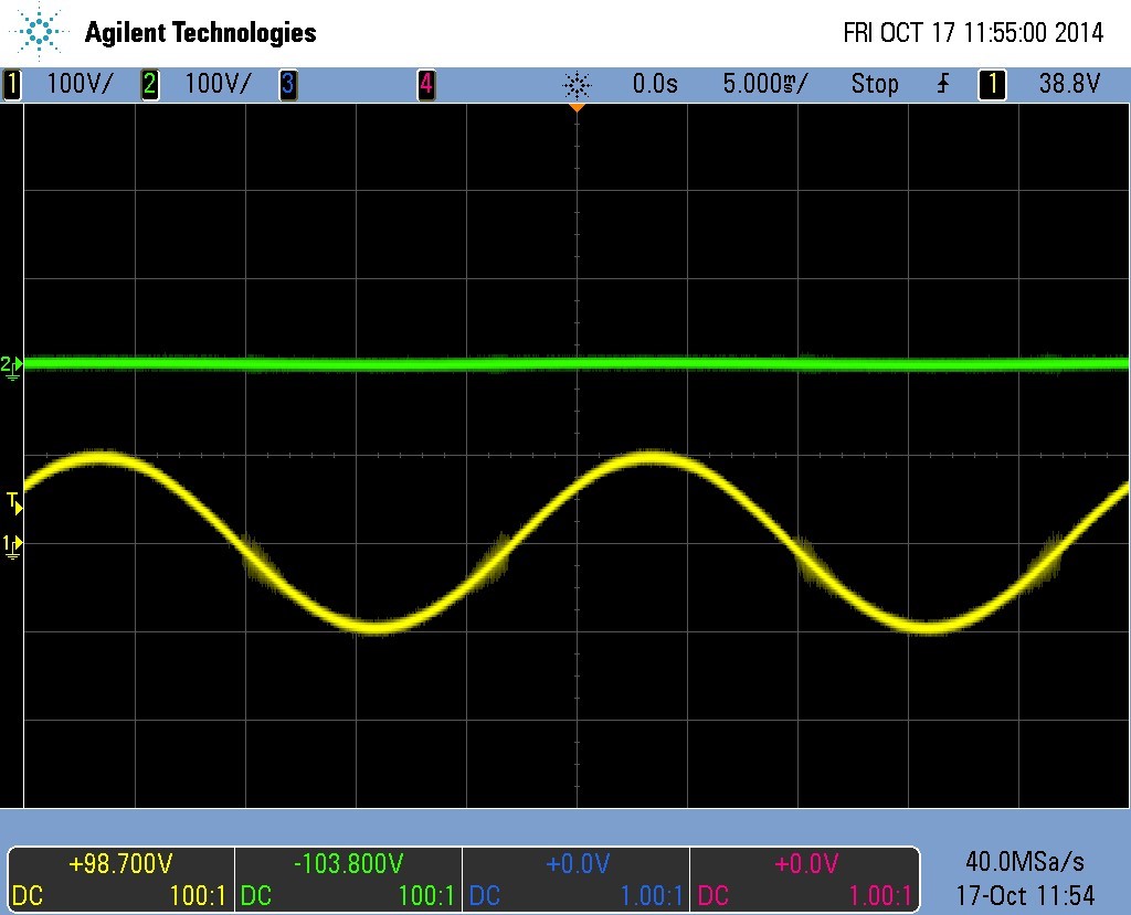
- 40Hz 2R, one channel driven, just before clipping. Took some effort to obtain this waveform.
- 40Hz 2R, one channel driven, when limiting. Significant out of band noise on the waveform crests
- Mains waveforms for 40Hz 2R, one channel driven.
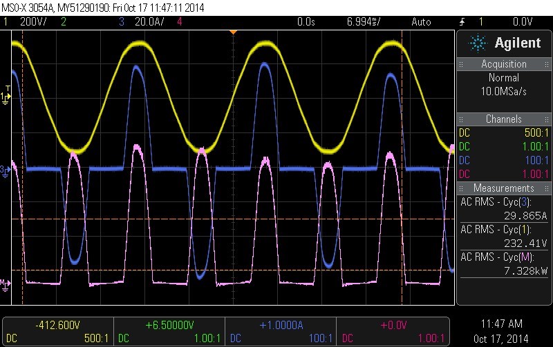
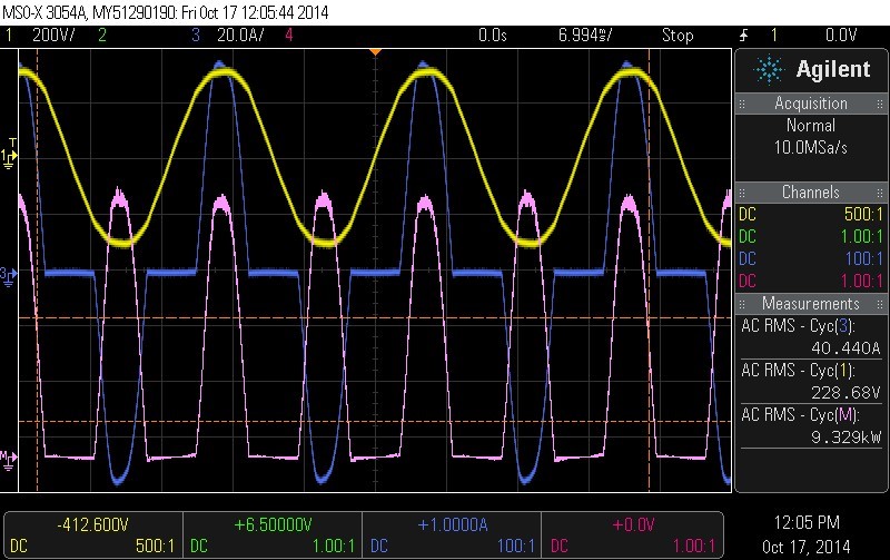
- 40Hz 2R burst power, full input signal allowing the amp to limit itself. 13A mains fuse blew within about 330ms of signal activation.
- Mains waveforms for 40Hz 2R just prior to fuse blowing.
- 40Hz 2R prolonged 1 second burst. No fuses blew. Source of asterisked 2R 40Hz result above.
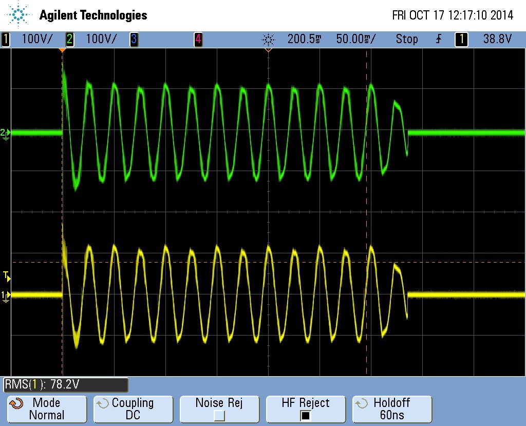
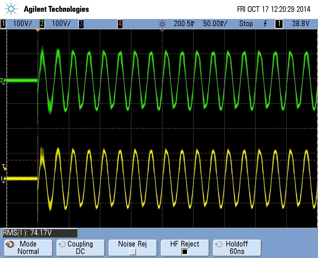
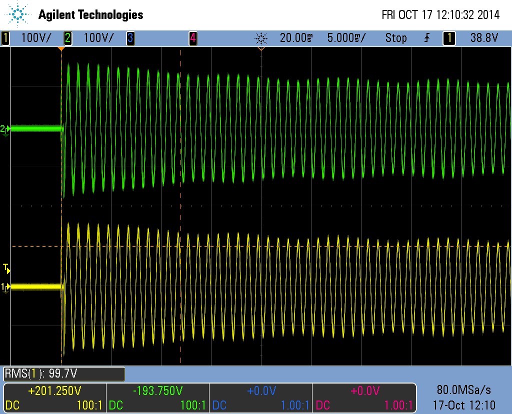
- 1kHz 2R short burst. No fuses blew. Source of asterisked 2R 1KHz result above.
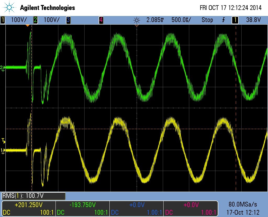
- Magnified version of previous waveform. Initial spike at turn-on is caused by switching on the signal generator. Lots of HF noise and visible distortion present on the waveform as the amp limits.
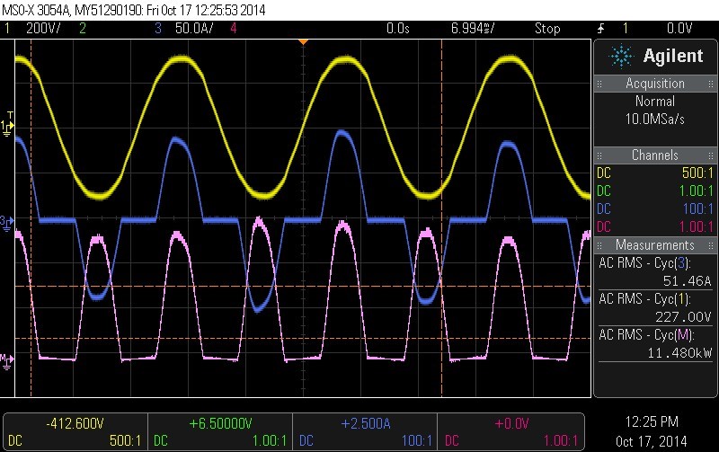
- Mains waveforms for 40Hz 2R, just after limiter has decayed the power somewhat. Note the 100A peaks on the current waveform.
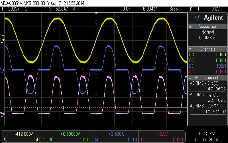
- 1kHz 2R prolonged burst, after limiting. Noisy waveform, out of band artefacts visible.
- Mains waveforms at 1kHz 2R.
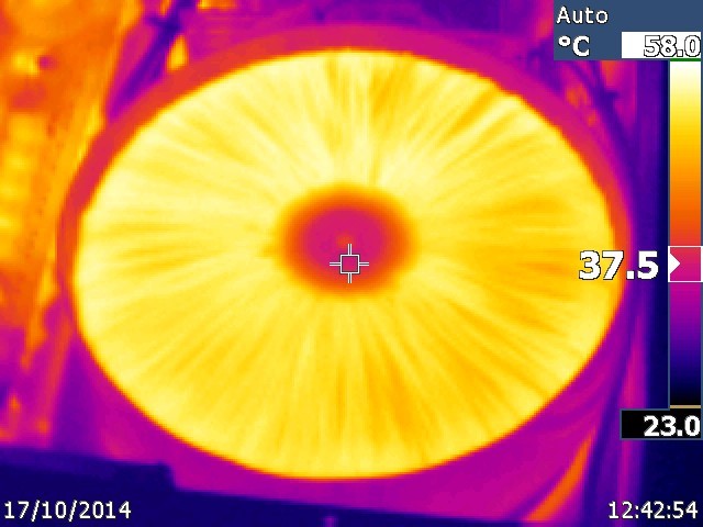
- Thermal image of toroid after running at 1kHz 4R full power with the lid off for 10 mins. No hot-spots, approx 55C.
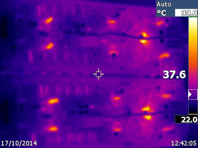
- Thermal Image of amplifier PCB, nothing untoward. Hot components are power resistors designed to run at high temperatures. All transistors are operating cool suggesting they are used within their safe operating area.
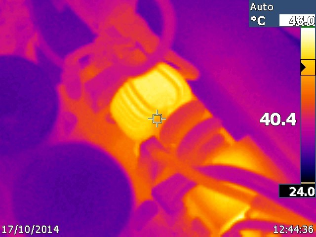
- Thermal closeup of the mains input section. The common-mode filter choke is running hot - it's unusual to find these fitted to toroidal amplifiers.
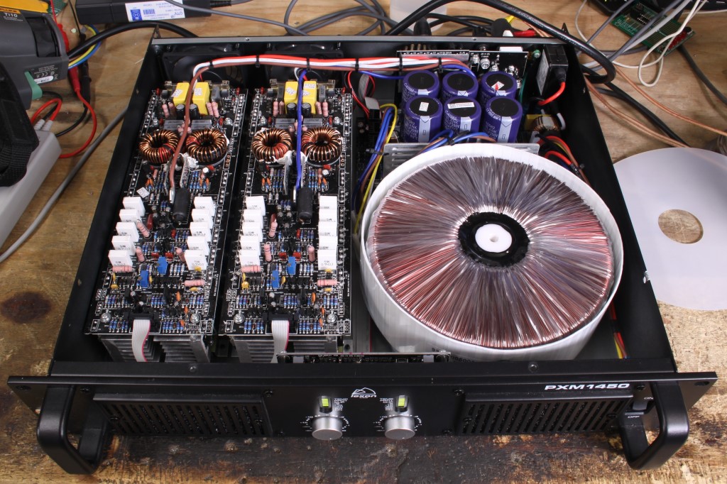
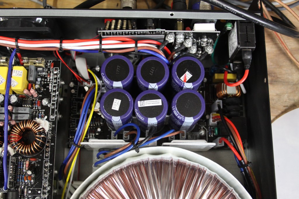
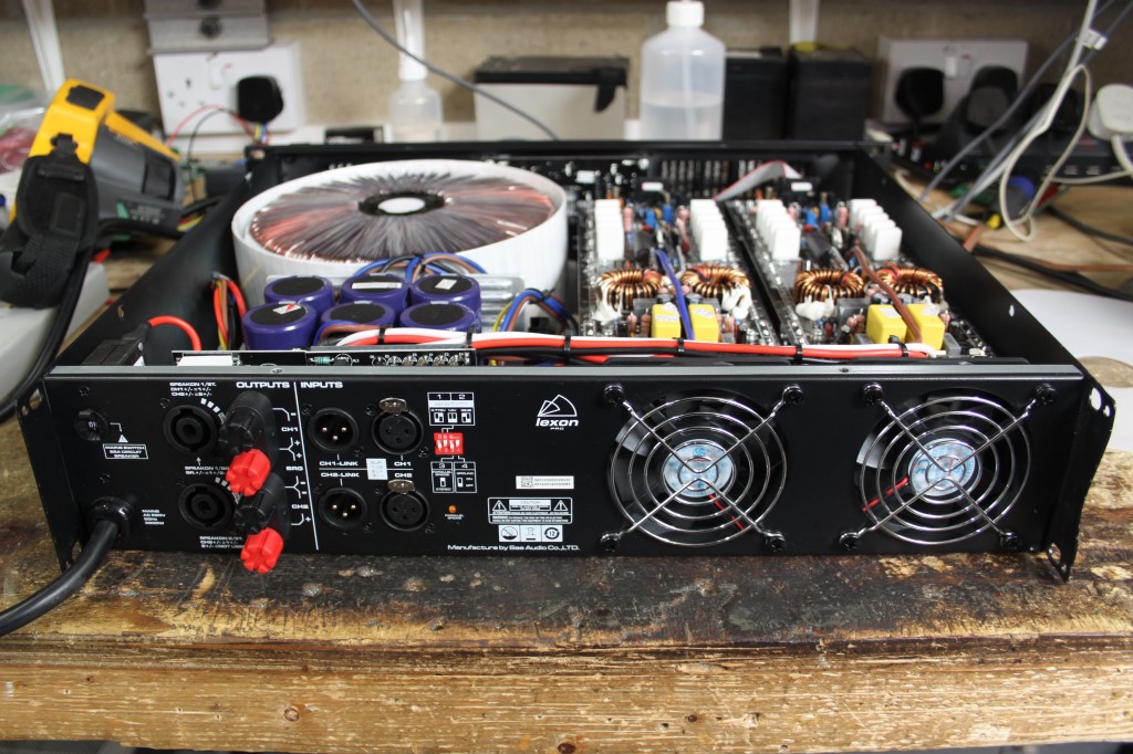
- Amplifier internals. Large toroidal transformer to the bottom-right, two independent amplifier channels towards the left, power supply smoothing capacitors towards the top-right.
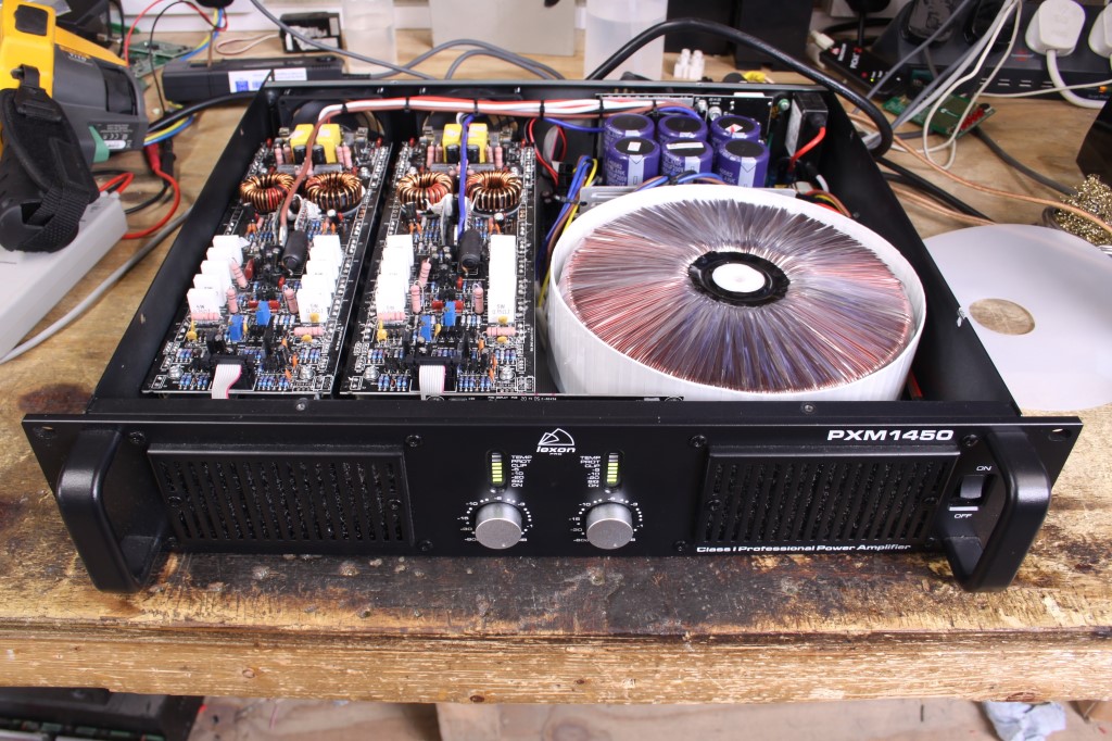
- Another shot of the internals. Front panel dust filters are easy to replace, and the power switch is recessed and protected behind a rack handle making accidental knocks difficult.
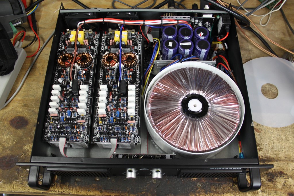
- Another shot of the internals
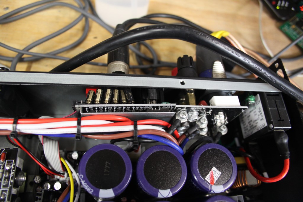
- Closeup of power supply smoothing capacitors. Relatively small for an amplifier of such high power, but very little 50Hz ripple bleeds through to the output.
- Audio input board is mounted slightly askew, and the photocoupler used as part of the limiter has its pins very close to the casework potentially shorting it out if the amp was subjected to shock.
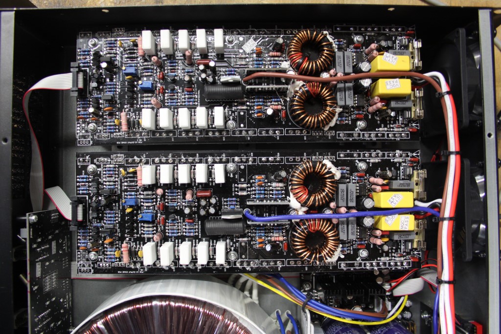
- Amplifier channels, each with a cooling fan. Front panel board is connected neatly with ribbon cable, and all internal wiring is neat and well tied.
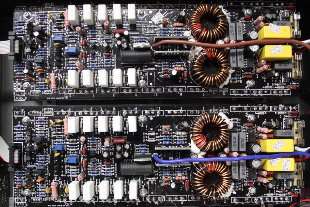
- Zoomed in version of previous image. the two large toroidal inductors per channel are the buck converters for the supply rail modulation. Neat and tidy symmetrical through-hole layout
- Rear of amplifier
